Firstly, I had to ensure that the vertices on the furthest right were all lined up in a straight line. This is so that we have a nice line to mirror across which will give a better join when the two parts are put together to form the full face.
As you can see from the image below, the points are roughly straight. However this is not good enough. I used the "Make Planar" tool and then aligned along the X axis.
The image below is the finished result once the points have been aligned:
Next, using the left viewport, with all those vertices still selected, I transformed the points in the X direction. The image below is what happened on my first attempt of this:
In theory, all of the points should still be in a straight line (excluding the gap where the lips and mouth go). This is an indication that the reference plates are too close together. After moving the side plate slightly to the right, I received the following result:

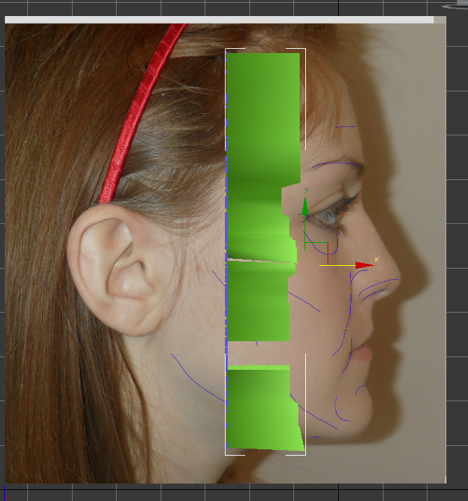
The shape produced was much better as it was much more solid than previously. Next, I made the mesh see through. This is to make it possible to see the guidelines to follow and make the modelling process much easier. I also froze the plates but had the "Frozen Objects in Grey" option unchecked to ensure that when I selected vertices, I only selected the vertices and not the plates themselves. Each of the centre points were then moved to line up with the shape of my face in the side on image as you can see from the image below:

For the next step, I made sure that edged faces were turned on. Again, this would make it easier to see which vertices I am moving and working with:

The next step is the one which I found the most difficult to do and was the most time consuming. This is because I had to keep switching between left view and perspective view to work out if I was moving the vertices in the right positions. It was important to only move them along the X axis because that is the axis that deals with the third dimension of the mesh, otherwise the changes would have an impact on the vertices that were lined up in the full frontal view. The image below gives an example of me moving the points to fit in with the shape of my face and also with the reference lines which I drew on using Photoshop.

This was completed for the rest of my face until I ended up with this:

I am very pleased with how my initial half face mesh has turned out. It did take me a few attempts though to get all of the vertices in the right place so it was very time consuming.
No comments:
Post a Comment