Now that the UVW Mapping co-ordinates have been positioned on one side of the face, it is now time to look at the other side of the face. Because the model will be identical both sides (due to the symmetry tool being used on the model) it means that the vertices will be in the same place, just mirrored.

In order to mirror the other side of the face, I ensured that select by object was on and then created a duplicate mesh which was positioned directly next to the other one. By clicking mirror, it reflects the mesh exactly, as you can see in the image below:

The matching vertices at the front of each of face mesh have to be welded together to form a seam which runs down the middle of the face. This is where the bump material will connect. Using the Weld tool shortcut (ctrl + w), once the vertices have been connected, the lines changed colour from green to white. Once that has been completed, the ear was copied and mirrored as well. Care had to be taken to ensure that the correct ear was selected and mirrored, otherwise the material will follow the wrong mesh.

Once this has been completed, the UMV Map Co-Ordinates was rendered and the following image was created:

This will then be used in the next blog post, which will involve creating layer masks to give a guide similar to the guidelines created on our image refernece planes. These will then be used to apply the images to and will go towards the final step, applying the material to makw it look more realistic.
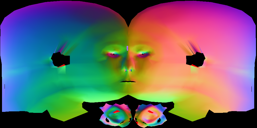
The map could also be rendered in different ways to demonstrate different things. The image below shows the normals which give an indication on how the finished mesh could look, taking into consideration all the changes to the UV co-ordinates.
No comments:
Post a Comment