Thursday 20 October 2011

Week 5 - Primitive Extension

The next stage of the head's development is to actually construct the back of the head. In order to do this, I had to make adjustments to the reference topologies to include reference lines for the rest of my head and my neck:


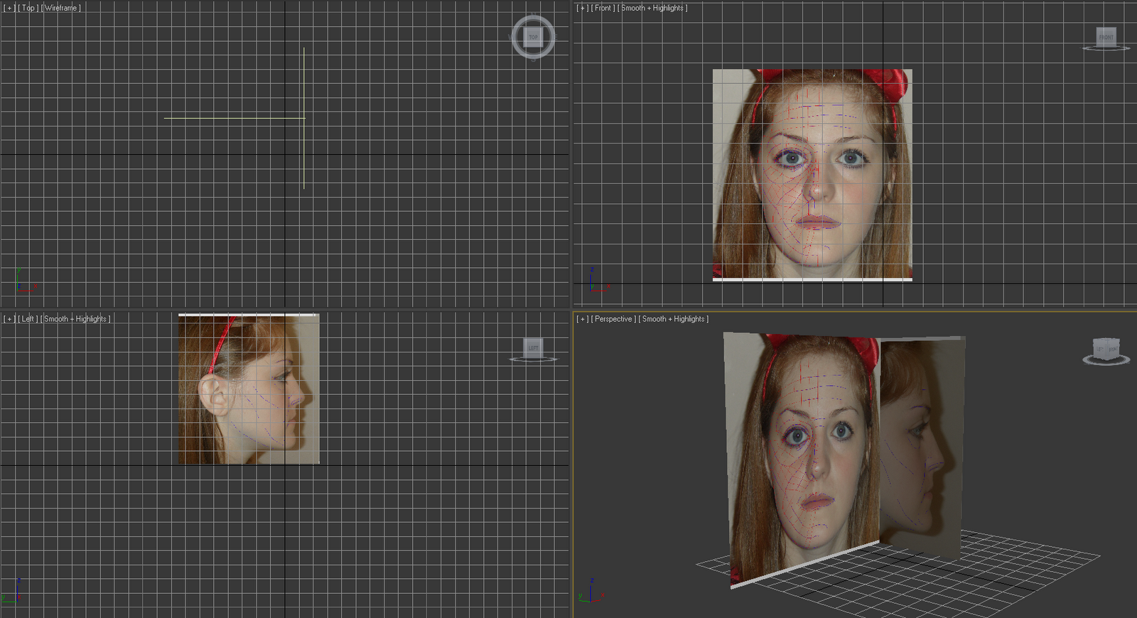
This was then imported into 3D Studio Max and used as a replacement to the images used before on my reference plates. Now, I was all ready to begin modelling the back of my head. First, I created a sphere roughly the same size as the back of my head and then rotated it by 90 degrees in two directions to give me the image on the right: 


Next, I resized the sphere to fit in with the size of my mask more accurately (see image below). In order to reduce the number of polygons on the sphere, I counted the number of polygons on one side of my forehead and reduced the number of sides until, using the edges as guides, both the sphere and the mesh lined up.  It does not matter if the sphere overlaps the mask because what had to be done next would rectify that.


Using the Paint Selection Region tool, I highlighted all of areas which I wanted to delete on the sphere. These polygons would not be used in the final model. It was also important to ensure that the polygons selected apply to both sides of the head.


The image below shows the remaining head segments. It was necessary to delete the right hand side of the head because, seeing as the mesh has a symmetry modifier applied to it, it would be a waste of polygons, which in turn would take it longer and use more resources to render.


One of the difficult parts of primitive extension tutorial video is to line all of the points up between the skull and the face. I made sure the snap tool was on to make it a bit easier for myself and to ensure that they were snapping to the correct vertices.

The image below shows the forehead connected to the skull:

One of my setbacks was that I incorrectly counted the number of polygons across the forehead of my mesh because of the viewport angle. This meant that I had to restart this section again (and will explain the differences in the colour between the images above and the following images below).

This is the finished skull after it had been jointed to the face mesh. The next step was to extend the polygons down the back of the neck and to join them up with the chin, connecting all the other polygons on the side of the face. However, in order to do that and to be more resourceful, I deleted some of the extra polygons that were not needed:

This is a before screenshot:


This is an after screenshot:


The image below is a screenshot of what my head looked like after I filled in all the polygons for my head and neck and then joint them together to form one object using the Attach tool. The result is far from perfect but it is a good start:


Snapshot of me attempting to remove some of the harshness between the joint using the Soft Selection tool. 

Unfortunately, I have run out of time to complete my face model before my unofficial deadline date to check to see how well my work is progressing, however I have a few weeks yet before my final deadline date. All this said, I am confident that with a little more time and some guidance I will be able to improve greatly on the work I have completed so far and, conducting my own research, apply hair to the head, eyelashes and eyebrows. I am very pleased with the way my work has progressed so far.

Week 5 - My final face mesh

Here is an image of my final face mesh. I am very pleased with how it has worked out. Obviously, there are more stages in the development of my full head and some adjustments will most likely be made but for now, I am very happy with how the face looks.


The next step is to extend the topology lines so I can make a start on the full head nad neck.

Week 5 - Defining the lips

The final part of defining the facial features involves the lips. This is very important because when I come to using the Morpher modifier to animate my final face, the lips will be a key part of the face that will move. Firstly, I separated the lips into polygons. This could be done one of two ways, by either adding polygons onto either lip so there are two sets of polygons or by created one set of polygons and then cutting them through the middle:


The next step is to move the polygons to give a more realistic shape:


This is the outcome after the mesh has been turbo smoothed. I am very pleased with the outcome.


For presentation purposes, I added a lip texture to the lips to show how well they are defined. When I use the UV Mapping later on in the project, the textures will be replaced.

Week 5 - Defining the eyes

The eyes did not need much work done to them for now. Firstly, I just made two spheres a placed them behind the mesh, as close to the mesh as possible. They do not look realistic at this moment in time but this will change once I have used UV Mapping. I modified the vertices surrounding the eyeballs to create a more realistic shape.

This is a before shot: 

This is an after shot (after turbo smooth):


Now i have to finish off the lips, before I can extend my head and neck.

Week 5 - Defining the nose

The next step was to define the features on my face, the first being my nose. The first thing I had to do was create more polygons in order to make it easier to shape. In order to do this, I used the Cut tool around the nostrils. After that was complete: I adjusted all of the vertices (which was trial and error in a way) to give a more realistic nose shape.


 The image below shows the next step, which was to divide the nostril into polygons:


However, after I did this and then moved them, I discovered I had a lot of issues where the mesh would just break: 


Because of this, I decided to remove the polygons and adjust my nose without them. I made a few changes to the nostrils to make them appear more rounded like my own nose. The image below shows my finished nose with the edged faces showing:

The idea for the nostril is to give a teardrop shape. I achieved this by selecting polygons and moving them to achieve the following result: 


 Now, I need to follow a similar kind of approach to complete the eyes and lips.

Monday 17 October 2011

Week 5 - Making minor adjustments

I thought I had better make some final adjustments to my mesh because i was unhappy with certain aspects of it. This is my original mesh straight from adding the symmetry modifier to it:


There are quite a few issues which were not apparent before I added the modifier because I only had one side of the face apparent and it looked like a close match to my reference plates.


The things which needed adjusting were: 
  1. Forehead - the forehead was too pronounced and needs to be smoothed out to give a more realistic look.
  2. Bridge of the nose - too thin and needs to be made thicker to fit in with the rest of the nose. 
  3. Face - slightly out of the reference plates. This is due to both the fact that I used the Turbo Smooth modifier and all my features were made too small and that one side of my face is slightly bigger than the other. 
  4. Eye position - slightly out of the reference plates. 
  5. Cheeks - too bumpy and need to be smoothed out. 
How these things were adjusted: 

  1. Forehead - I moved the vertices and edges of the forehead to give it a flatter appearance. I found that using the perspective viewport really aided in this, so that I had a bird's-eye view of the top of the forehead and therefore making it easier to ensure that I am moving the correct points.
  2. Bridge of the nose - was adjusted by moving the vertices which linked the nose and eye together further towards the left position along the X direction. This error was possibly due to not following the reference plates as closely as I should have.
  3. Face - I made the face bigger and realigned the new face shape. This looked much better than previously, however it did mean that my mouth is slightly out of the reference plates. However this should not be so much of a problem because I can just move the reference plate.
  4. Eye position - This issue was corrected when I adjusted the bridge of the nose.
  5. Cheeks - These were smoothed out in a similar way to the forehead.
 This is the result after all of the above were applied:


I was still very unhappy with the material effect on my face so I modified the material to make it less shiny:

After applying a lighting effect:


I am very pleased with the final effect of my face mesh and I am now willing to proceed with the finer details, such as the nose, eyes and lips.

Week 5 - Mirroring the mesh

The next step for my model was to mirror my mesh so that I would have a full face mesh. The video tutorials gave different methods which can be used to do this (for example, the mirror modifier and the symmetry modifier) I decided to use the symmetry modifier because if you edit one side of the object, it will always be duplicated on the other side and it does not matter on the viewport's current position. However, when you mirror an object, the viewport's current position is taken into account and if it has not been set up correctly, any adjustments made will be displayed differently on the mirrored object. Also, if the model is exported or imported into a different piece of software used for editing 3D, the vertices on the cloned side of the face would be inverted using the mirror modifier, but they would not be inverted if the symmetry modifier is used. In the instance of this project and the face should look roughly the same, symmetry is the best modifier to use for the job.

After applying the modifier, the viewport looks like this:


Initially, the modifier has placed the symmetry the wrong way and only displays in the middle of the face. To correct this, I flipped it and moved the clone out so that the the two sides are only just joining in the middle. The image below shows my face mesh after these steps were carried out: 


 I modified the mesh colour just for the time being to make the "skin" look more realistic. I then used the Turbo Smooth modifier to smooth the mesh and give the face a more natural shape. The image below shows my final result: 


Week 5 - Extruding the mesh

This week, I had to build on the half a face mesh which I made last week. The aim is to extrude the points on the face in order to give it a third dimension. This will then be mirrored in the next post.
Firstly, I had to ensure that the vertices on the furthest right were all lined up in a straight line. This is so that we have a nice line to mirror across which will give a better join when the two parts are put together to form the full face.

As you can see from the image below, the points are roughly straight. However this is not good enough. I used the "Make Planar" tool and then aligned along the X axis.
The image below is the finished result once the points have been aligned:
Next, using the left viewport, with all those vertices still selected, I transformed the points in the X direction. The image below is what happened on my first attempt of this:  

In theory, all of the points should still be in a straight line (excluding the gap where the lips and mouth go). This is an indication that the reference plates are too close together. After moving the side plate slightly to the right, I received the following result: 


The shape produced was much better as it was much more solid than previously. Next, I made the mesh see through. This is to make it possible to see the guidelines to follow and make the modelling process much easier. I also froze the plates but had the "Frozen Objects in Grey" option unchecked to ensure that when I selected vertices, I only selected the vertices and not the plates themselves. Each of the centre points were then moved to line up with the shape of my face in the side on image as you can see from the image below:


For the next step, I made sure that edged faces were turned on. Again, this would make it easier to see which vertices I am moving and working with: 


The next step is the one which I found the most difficult to do and was the most time consuming. This is because I had to keep switching between left view and perspective view to work out if I was moving the vertices in the right positions. It was important to only move them along the X axis because that is the axis that deals with the third dimension of the mesh, otherwise the changes would have an impact on the vertices that were lined up in the full frontal view. The image below gives an example of me moving the points to fit in with the shape of my face and also with the reference lines which I drew on using Photoshop.


This was completed for the rest of my face until I ended up with this:


I am very pleased with how my initial half face mesh has turned out. It did take me a few attempts though to get all of the vertices in the right place so it was very time consuming.

Week 5 - Illness

Due to illness, I have been unable to complete as much of my face as I would have liked to. I have my first deadline this Friday however, because it is only an informal hand in and an assessment on how well we have done at the moment, I am not too concerned. Providing I manage to organise the rest of my modules which will mean I have more time to complete my face model to the best of my ability, then I should be able to reach my target grade. The next few posts will show what I did in the next stages of development last week, seeing as I was not well enough to post them at the time.

Monday 10 October 2011

Week 4 - My thoughts so far.

The work on my head needs to be handed in in less than 2 weeks time and at the moment, I am a little apprehensive towards my progress. I have had so many setbacks over the past 3 weeks, I am really nervous that I will not meet the deadline on the 21st October. However, I will spend more time on this project than my other projects which are ongoing at the moment and hopefully I can turn this around.

As for the modelling methods that are being used, I am finding it fairly easy to follow the video guides that have been given to us and I am really improving on my modelling skills. However, there have been many setbacks due to either loss of judgement or using the wrong version of the program. If I begin to plan my time more fully and set up a timetable which I can follow to finish my work, I should be ok.

Here is my mini time plan:

Week 4 - Making my face into a mesh

Next, I had to create a workable mesh using the line tool in 3D Studio Max. I used the lines which I drew on my face image in Photoshop as a guide so I knew where the lines should go. The idea was to separate my face into a series of quadrants (4 sides polygons) while limiting the number of 3 sides polygons because they are more difficult to work with. Unfortunately, especially towards the side of the face, there were a few 3 sided incidences however this should not cause too many issues. This will then form the base mesh. In the images below, you will see the progress of my mesh from half way through to the end.


Halfway through: I have concentrated around the eye to keep as close to my original markings as possible to give the most realistic outcome.


Finished: I have followed almost all of the lines which I added onto the original photograph in Photoshop. If I need to make any adjustments to the mesh, it can be done later after I experiment with the Attach tool. However, from first glance, there appears to be nothing wrong with the mesh and I should have only limited issues such as small gaps where the lines haven't connected properly. 
Next, I converted the top quadrant to a polygon and then used the Attach tool to select all of the lines in the mesh and join them together because at that moment, they were acting as separate shapes and not as one whole polygon. 


However, once this was completed, it became obvious that there were gaps in the mesh which needed to be corrected: 


In this screenshot, you can see the gaps just above the eye. In order to fix this, I used the weld tool.


The idea of the weld tool is to join polygons together (which would in turn remove all of the unwanted gaps in the mesh) in order to reduce the number of polygons down to make it easier to model with. Otherwise, it could be much more fiddly and tricky than it needs to be.


This image is the before screenshot, which shows the original polygon count and what it will be reduced to after just one increment. It is important that the threshold increase is not too much; otherwise the wrong polygons will be joint together as well.


However, after completing these steps, I realised that I forgot to make a hole for the nostril. This is a mistake because I will need a hole in the mesh (similarly to the eyes and mouth) so I would be able to model the nose correctly and make it look realistic.


I also noticed that the nose shape did not look very realistic and I had missed out several lines which would be vital in creating the bridge of the nose. So I had to make adjustments.


This is the new mesh with the nostril and the additional quadrants added:


The final step in this stage was to move the planes and freeze them in place for the next step which will be posted in another blog entry.

Week 4 - Issues RESOLVED

The file load issue has been resolved now. I was using the 2010 version of 3D Studio Max instead of the 2011 version which is used on the university computers. 3D Studio Max now works and I am able to continue with my project.

Sunday 9 October 2011

Week 3 - Issues with loading 3D Studio Max File

Today, when I came to open my work to continue with the next step in the design process (I had already separated my face into vertices and only had to do one more thing to obtain the shape of the face) I kept receiving the following error:


This occurred with my back up file as well. I have emailed my tutor to find out what steps I can take to hopefully retrieve my work, otherwise I will need to repeat all of last week's work again. I have no idea why the file has corrupted as it appeared to work on the university machines where I had saved it, plus I have tried both x32 and x64 bit versions of 3D Studio Max.

Until then, I am continuing with my other modules and my group work Virtual Environments assignment.

Friday 7 October 2011

Week 3 - Finishing my Reference Planes

In the tutorial today, I made the reference images (which was created in Photoshop) into the reference planes that I will need in 3D Studio Max.

Firstly, I cropped the images so that they were of usable size and then I saved them as a different file name. After opening 3D Studio Max, I created a vertical plane and ensured that I modified the number of length and width segments both equalled to 1:


Then, I imported the images onto the plane.
Using UVW Mapping, I moved the image on the plane so that you could see a full frontal view of my face:


Then, I copied the plane and rotated it sideways. Using UVM Mapping again, I moved the image so that you could see the side of my face and flipped it so that it fitted in with the front view.


This is the final result: