Monday 19 December 2011

Evaluation

Evaluation of my work

Discussion

Overall, I found this part of the module very difficult because of the following reasons:
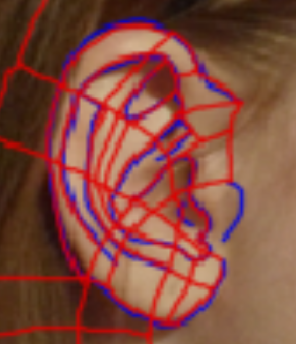
  1. Some parts of the videos that I had to follow were not explained very clearly or were skipped entirely, particularly the primitive extension part of the assignment where the eyes and lips had to be refined and when the neck had to be extended from the rest of the head. 
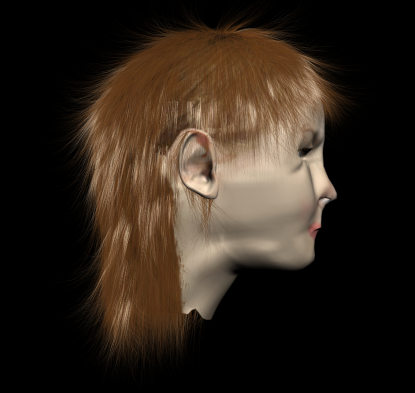
  2. The videos worked well for male models who had little hair, but for someone with long hair and a fringe, I found it incredibly difficult to accommodate these differences, especially as there was a break down in communication and for a couple of weeks I was using wrong reference images. 
  3.  Time has been really pushed to complete this and the Guildhall project so on occasions, we had to cut our losses. Some work could have been completed better if we simply had more time to do it. 
However, I do believe that considering the set backs, the inconveniences and the time constraints, I have achieved a model which works to the best of my abilities. 

My Individual Strengths 
  • 100% attendance meant that I did not miss any lessons in class, which gave me more time to complete this part of the module, though it has been pushed for time if you consider other modules and other assignments. 
  • I learnt new skills which I did not know before which will definitely come in handy in other projects in the future or in a working situation.
    • I managed to cope with the stress I was put under from my other modules and still complete my work to a good standard. 
    My Individual Weaknesses
    • Limited knowledge of 3D Studio Max when I first started out because I missed the majority of my animation work last semester due to illness. 
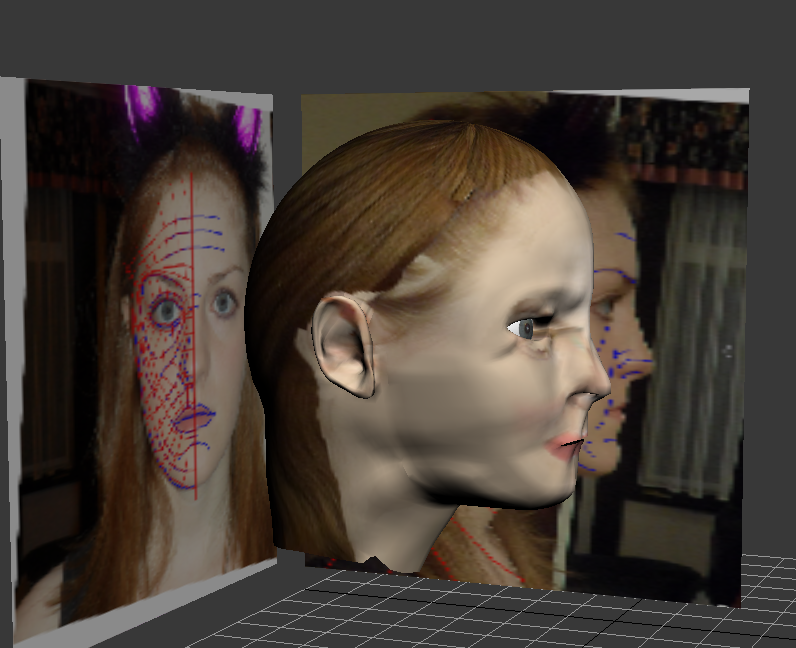
    • A break down in communications between the class and lecturer meant that some members of the class did not know that there were issues with their images and this affected me in particular (which in turn affects topology, which affects primitive extension, which effects the UVW mapping, and in severe cases could affect the animation as well) and we did not find this out until our results from the halfway point were given back to us at the end of week 8/beginning of week 9. 
    My Improvements For The Future
    • Take some time before the project begins to research any tools or software which I am not very familiar with as this will save time in the project for either asking other people for help or researching partway through the project.
    • If any issues occur in the future regarding the lecturer, speak to someone about it to get it resolved as soon as possible to avoid this kind of thing happening in the future. 

    Animation using Morpher

    The final part to this module, which was to be completed as additional work, was to animate my face that I have created using the Morpher tool. In order to do this, firstly I ensured that the hair and fur modifier was turned off. After converting the original face to an editable poly, I created 4 clones and positioned them side by side: 


    The next step was to make edits to the faces to add emotions and rename them in order to make it easier to link the cloned faces to the original:


    Then, after applying the Morpher modifier onto the main object, I linked the other faces accordingly:


    Clicking the up and down arrows allows you to see a transition between the original model and the clone. This will help when it comes to creating a rendered video with the Auto Key tool.

    The image below is a render which I did of the surprised face. As you can see though, because there is a hole between the lips to allow room for teeth, for example, if there was more time in the future to complete the project, you can see the hair coming through the module at the back. As a small measure to correct this seeing as there is not enough time to do anything too drastic this close to the final hand in date, I inserted a small primitive box shape and coloured it dark to look like the inside of someones mouth.


    Surprised face corrected - raised eyebrows and mouth open:


    Closed eyes - perfect for blinking: 


    Smile!! - corners of eyes adjusted and sides of mouth adjusted too:


    The short video clip below shows my final model animated:


    And that concludes this part of the module!

    Adding Hair

    Applying hair and fur is a new technique which I have never used before. Due to lack of time, I did not have much time to experiment with it, therefore it did not match my face as it should, making it a little unrealistic. Still, I thought it would be a good idea to display my experimentation anyway. 

    I selected the polygons I wanted to apply hair to first of all. The annoying thing about hair and fur is that you have to keep producing renders to see what you have changed in each stage.  In the image below, it simply just shows where the hair has been positioned on the model: 
        

    This is where I removed any hair which I accidentally put on my neck using the haircut tool. I then used re-comb to reshape the rest of the hair and changed the hair colour so it is closer to my natural colour.


    Here is the render of my hair with the reference planes included:


    This is my final face model after it has been rendered with all the reference planes hidden:


    This is a side view of my finished head model: 


    Overall, I am very pleased with how my model turned out, even though it does not really look like me all that much. If I had more time in the future, I would concentrate more on trying to fix up the hair and remove the pinching near the eyes.

    Sunday 18 December 2011

    Back Into Photoshop!

    Now it is time to go back into Photoshop to sort out the images and prepare them for the bump painting which is the next step. I created a copy of the UV co-ordinates map render and opened it up in Adobe Photoshop. A new layer was created and was coloured a different, bright colour to make the topology very easy to see, and therefore making the material matching up phase easier for myself. 


    Using Quick Mask mode, it allowed me to select just the topology lines. I ensured that the line select thickness was set at 4 in order to make the topology more easily seen.


    This was then pasted over the top of the black layer and I exited Quick Mask mode:


    Once the layer mask has been added to the layer, it will go transparent:


    The next step was to copy and paste parts from my reference images and match it up to my topology. The image below shows the beginning of this process: 


    This is the topology part of the way through. I found it very difficult to match up because each side of my face is a different shape. So I tried cloning and copying the other side of my face to make it look more symmetrical. While it may not look as realistic for now, it will look better once it has been applied to the actual model. 


    The next issue I encountered was that half of my face was a different colour in the reference images due to shadowing caused by the environment lighting. At first, I was unsure how to fix this however, I found that if I modified the exposure levels, I could match up the colours quite nicely:  


    I thought it would be a good idea to put my mesh as it is at the moment into 3D Studio Max to see how well it fits to the model. To make it look more realistic, I created a cut out from my eye and used that as a material for my eyeballs: 

    I decided to apply the image to my face to see how it looked, there were still issues with one side of the face being too dark so I went back into PhotoShop and made the necessary adjustments. Overall though, I was very pleased with how well the material was fitting to my face: 


    In the image below, I managed to equalize the skin tone to match the face so it looks Nearly finished! Just need to line up the ears because they managed to fit in the space after some tweaking. I also need to remove the shadows from the chin and the side of the face to even it out.


    Nearly there now! There are a few issues with the hair at the top of the head and also there is not a smooth transition between the two different sides of the head. 


    This a side view of my finished UVW Map material. Overall, I am very happy with it, particularly the ear because the material fitted perfectly and it looks very much like my own ear now. There is some pinching near the eyes however due to time constraints, I will not have time to go back and sort out these problems. 


    Another view: 


    Friday 16 December 2011

    UVW Mapping - Symmetry

    Now that the UVW Mapping co-ordinates have been positioned on one side of the face, it is now time to look at the other side of the face. Because the model will be identical both sides (due to the symmetry tool being used on the model) it means that the vertices will be in the same place, just mirrored. 


    In order to mirror the other side of the face, I ensured that select by object was on and then created a duplicate mesh which was positioned directly next to the other one. By clicking mirror, it reflects the mesh exactly, as you can see in the image below:


    The matching vertices at the front of each of face mesh have to be welded together to form a seam which runs down the middle of the face. This is where the bump material will connect. Using the Weld tool shortcut (ctrl + w), once the vertices have been connected, the lines changed colour from green to white. Once that has been completed, the ear was copied and mirrored as well. Care had to be taken to ensure that the correct ear was selected and mirrored, otherwise the material will follow the wrong mesh.


    Once this has been completed, the UMV Map Co-Ordinates was rendered and the following image was created:


    This will then be used in the next blog post, which will involve creating layer masks to give a guide similar to the guidelines created on our image refernece planes. These will then be used to apply the images to and will go towards the final step, applying the material to makw it look more realistic.

    The map could also be rendered in different ways to demonstrate different things. The image below shows the normals which give an indication on how the finished mesh could look, taking into consideration all the changes to the UV co-ordinates.

    Thursday 15 December 2011

    UVW Mapping - UV Co-Ordinates for the ear

    Now that the face and head UV co-ordinates have been positioned correctly, it is now time for the ear. I found the ear much more tricky because there were a lot more overlapping faces, particularly where the ear joins to the head. Like when I created the UV co-ordinates before, I selected the ear. However, instead of using a cylindrical map, I used a pelt which is more suitable for more detailed and complex shapes.


    After clicking edit to edit the map, I was shown the image below: 


    In order to flatten the faces of the ear mesh, I had to use the relax tool, similarly to when I trying to flatten the eye and nose mesh. As you can see from the image below, although there were a few problem areas, they were easily fixed manually by using the move tool.


    This is much better than how the ear UV co-ordinates looked previously. However, the co-ordinates are disproportionate to the rest of the head. This indicates that the map is much larger than the head and this will be rectified in the next step.


    Next, I unhid the unselected objects and as I mentioned above, the ear is much bigger than the head. I resized the ear to make it more proportional.


    Just to check the ear map is still in a good state after resizing, and making any necessary adjustments to reomove overlapping and inverted edges.


    The ear was then positioned inside the ear for fit. The fit was not exact though so the ear has been moved away for now. It just means that I have to be extra careful when it comes to seams around the ear after applying the bump material.


    UVW Mapping - UV Co-Ordinates for the face and head

    The next stage of the modeling process involves adding a bump texture onto the model to make it look more like me. However, before I could do this, I had to ensure that I mapped the UV co-ordinates correctly. I had to select the faces that I wanted to be impacted and then I applied a cylindrical map and modified it so that the head fitted inside perfectly. 


    The image below shows the UV co-ordinates and how the material would be distributed around the head. The idea is to have as many regular squares as possible. As you can see, there are a couple of problem areas that need rectifying, namely the top of the head and the neck.


    The image below shows the UV map in it's current unchangd state:


    Once placed into vertex mode, the vertices can be repositioned in order to correct the problem areas:


    Once the top of the head and the neck had been sorted, it was time to move onto other areas of the face where there could potentially be some issues; the eyes and the nose. The image below shows a much improved mapping across the top of the head:


    Onto the eyelids first, as you can see, there are a lot of overlapping faces which would cause havoc when trying to position a mesh.


    After using the relax tool which relaxes all of the vertices so that they have the minimal number of crossings and overlappings, there are still many vertices which are still very close together and could cause a pinching effect.

    After moving all the vertices out so that they are not so close together, this is the finished result:


    The next problem area is the nostrils. There are many overlaps here which need addressing:

    Again, using the relax tool seperates the vertices from each other, so that there are no more crossings or overlaps. However, simialrly to the eyes, the vertices have been positioned too closely together.


    So using the move tool, I spaced them out manually. This will give a much better and smoother effect once the material has been added.


    The image below shows the flattened face and head UV co-ordinates mesh.

    Tuesday 13 December 2011

    Creating the Ear

    The next video explains how to create an ear topology to add to the head model. The reference planes used in the head model were reopened in Photoshop and the ear section was modified. Similarly to the face reference planes, the ear was split up into blue and red lines which signify all of the polygons that make up the ear and where there are peaks and troughs to define the ear shape:


    After importing the new reference plates, the outline was traced using the line tool. If any of the lines were either too close together or did not fit in with the rest of the face topology, it was very easily corrected by realigning some of the lines and adding in a few extra quadrants. The image below shows the finished topology:


    One of the lines was selected and converted to an editable poly and then the attach tool was used to attach the rest of the lines to convert them to editable polys as well. As you can see from the image below, all of the segments are four sided which will make it easier to model and define.


    The next image shows the beginning of the extrusion of the vertices. I started off with the outer edges first and gradually got closer and closer to the middle. The vertices were arranged according to where the troughs and peaks were so that it looked more like my own ear.


    The image below shows my finished ear with a TurboSmooth modifier on it. I was very pleased with how it turned out because I felt it replicated my ear well.


    The next step was to extend the polygons and fold them back so that they could connect to the head. I found this part particularly difficult because I had a lot more polygons on the ear that I did on the side of my head, so it was very difficult to match them up exactly. The image below demonstrates how the polygons were folded back:


    The image below shows the final result once the ear has been attached to the head before smoothing:


    This is my head at the end of this stage without the TurboSmooth modifier on:


    The image below shows my head model at the end of this stage with the TurboSmooth modifier on. I was not very happy initially because there was a lot of pinching, particularly where additional polygons had to be added to the head in order to connect the vertices properly. However, I managed to smooth out the majority. This may not necessarily be a complete disaster though because the head model will look better once the UVW Mapping has been completed and, if there is enough time, hair has been added to the model which will hide the majority of the mistakes.